
The making of A Scanner Darkly
“Every breath you take, every move you make, every bond you break , every step you take, I’ll be watching you.”
A few months back I was standing in line to check out in my local Home Depot’s garden center. My mind started wandering until my eyes landed on a security camera that looked onto the line. It wasn’t a particularly uncommon thing to see in the store, but in focusing on that one location, I was keyed into the fact that I was being observed.
So I counted how many cameras I could see, and by my count, there were 7 cameras that were pointed at the checkout line I was in. Some were overt, others partially concealed. The overall effect of which was that I knew, on no uncertain terms, that I was being watched and recorded.
Experiences like that have become common now, where the infrastructure of surveillance has become so commonplace that sometimes we don’t even see it. But we know we’re being recorded. Be it from a video doorbell, cameras in a parking lot, or via 24-hour planes that record every person in a city, the feeling of being watched has become commonplace.
Now, I’m not an expert on Foucault, but his idea of the Panopticon is apt here. We change our behavior based off of whether or not we believe we are being observed, especially by those in power. All of these cameras moderate our expression, and are just part of larger systems that allow those with the cameras to have more power. What underpins all of this though are the laws that allow those systems to exist. The camera’s themselves don’t mean squat unless the things they record are allowed to be used in a legal setting. The laws are the pieces of surveillance infrastructure that the system work, even to a greater degree than the cameras themselves. They are created abd operate with some of the least scrutiny. How to show both the apparent and less-obvious sides of surveillance?
Thus, the concept for A Scanner Darkly.

Early Sketch showing how the piece was to be installed.
Starting out, I knew a few pieces about how I wanted this to come together - For one, that the faux cameras would be 3D-Printed, that I’d use existing tech for focusing the lights, and that it’d all run over WiFi. Most of those choices stemmed from a desire to simplify the construction of the piece, and allow for flexibility in its setup. If I could design every part of the faux cameras, it would save me a ton of hassle in trying to source and subsequently modify existing security camera bodies. That said, it cost me a ton of time down the road.
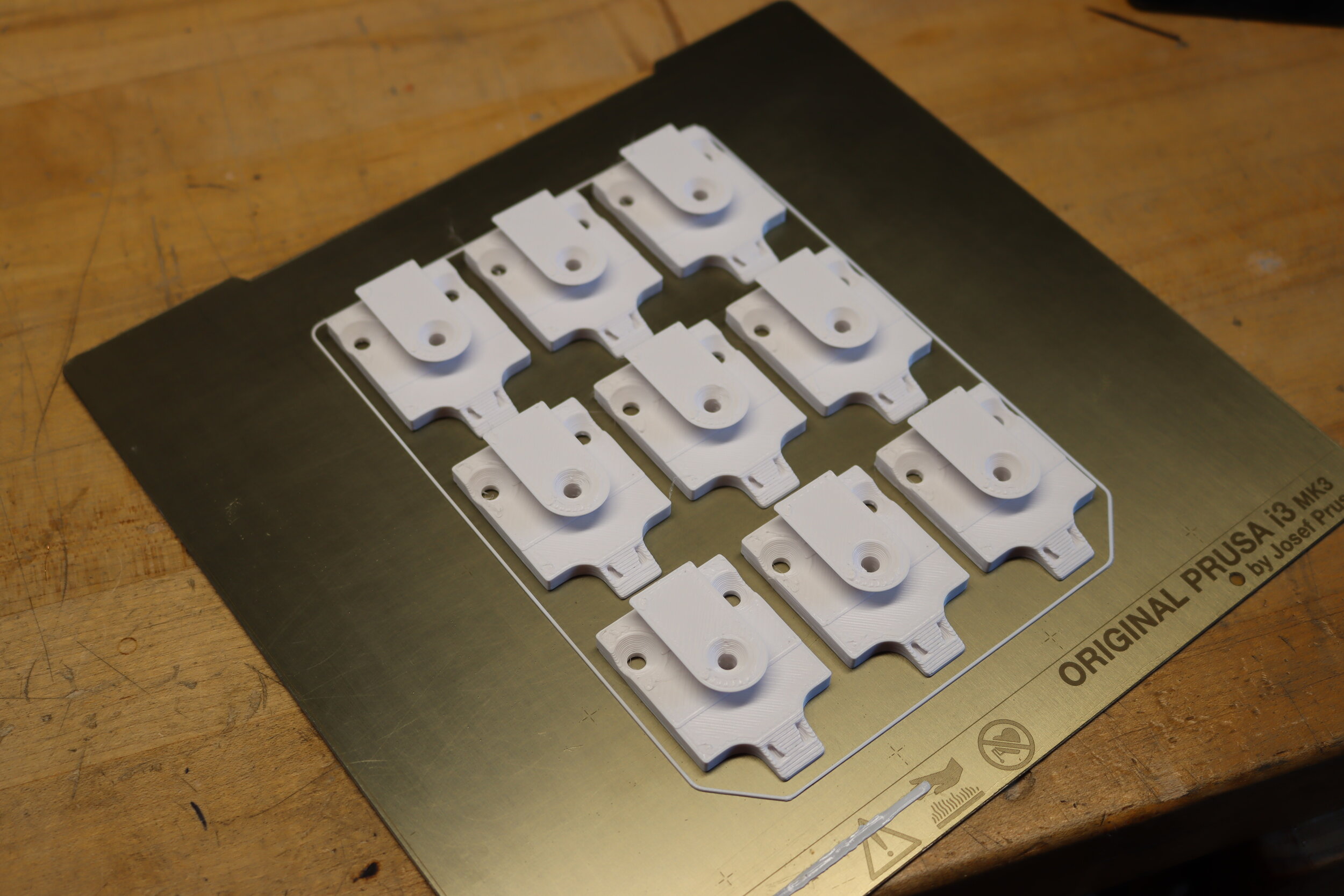
In making the security cameras, I’d put together a model a few years back that was optimized for printing in 8” cube print bed. It’ composed of a number of easy to print parts that are held together with tension.


I modified this file a few times through the process to adjust for printability, reduce needed plastic, and to make revisions for pieces I’d forgotten to include. In the end was a design that I was quite happy with, and that could be printed fully in just under 14 hours of machine time with a 0.8mm nozzle. The problem was that I had to make a 16 of them.
So I got to printing…

I also set up a nifty lil timelapse rig using my old DSLR and Octoprint


That time-lapse shows just over 4 hours of printing for two identical pieces, the lids that cover the pieces. All told, it ended up being over 230 hours of printing. So much that I ended up getting a second printer - A Prusa Mini - to complete all the pieces in the timeframe I had to complete the project. Had I not been using a 0.8mm nozzle and printing at a 0.6mm layer height, this easily could have run into the thousands of hours for printing. All told, 12kg of PLA filament went into making 16 usable faux cameras (and a few failed prints).
Next up was the process of finishing out all of the prints. While it’s all well and good to have a raw 3D print as a sculptural object, the thick layer lines and the artifacting from printing fast would have been distracting. Instead, I opted to smooth them out. To do so, I ran a sample finishes using a test print. I cannot stress enough how important this was, as I’d thought I’d be all right in just using sandable primer and paint, without pre-treating the surface of the prints. I was very wrong, and the tests showed that readily. The process I settled on was an initial sanding with 80 grit to knock down the rough edges of the PLA, twice using Rustoleum sandable filler primer with a 120 grit sanding fill in the gaps and smooth it out, some light bondo to fill any stubborn gaps, and finally two coatings of matte white spray enamel to finish them out. The finishing out of the prints took another 55 hours to complete.


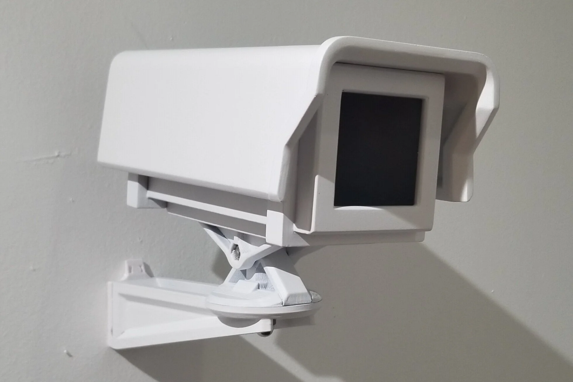
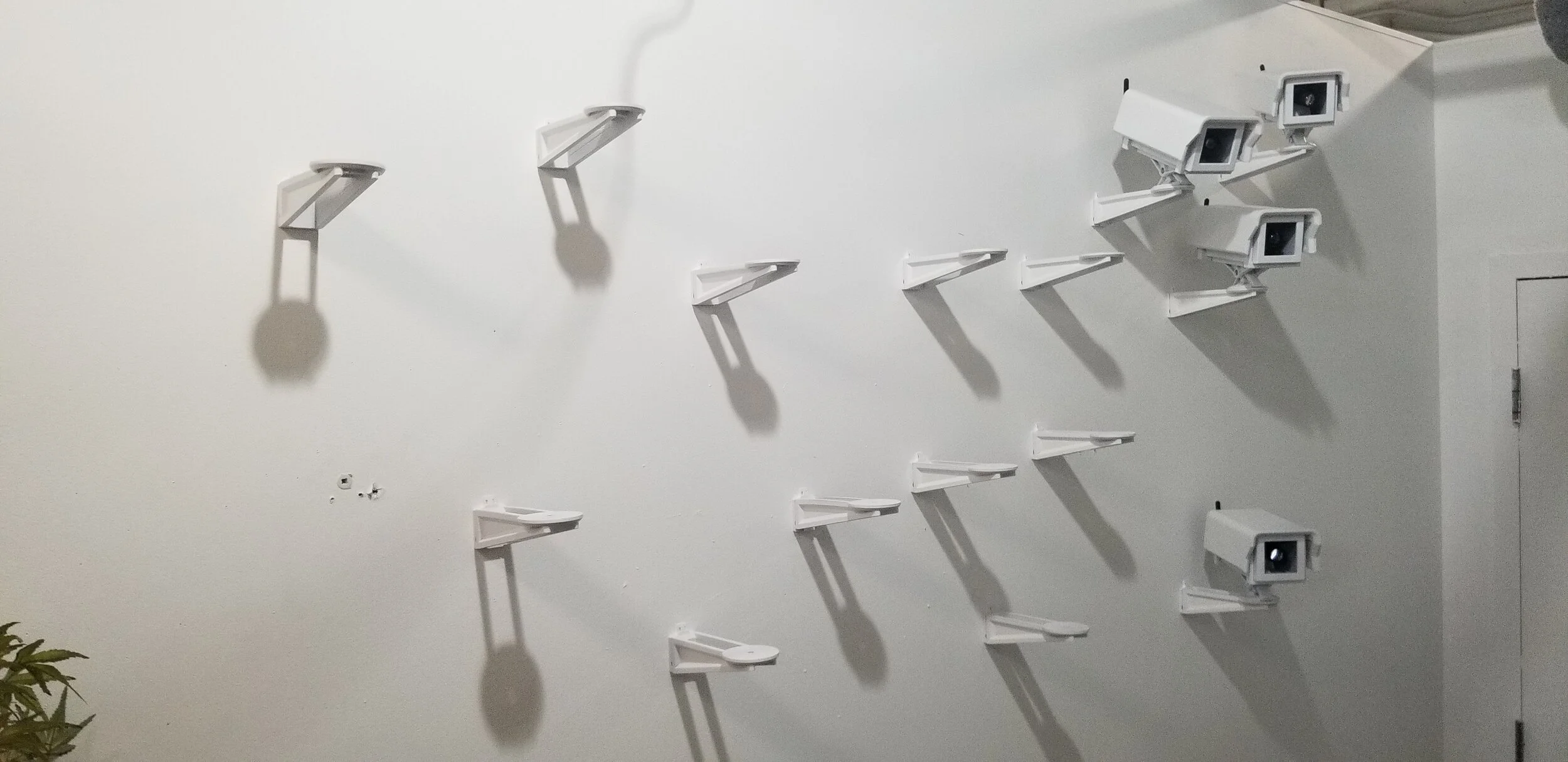
The finished result.
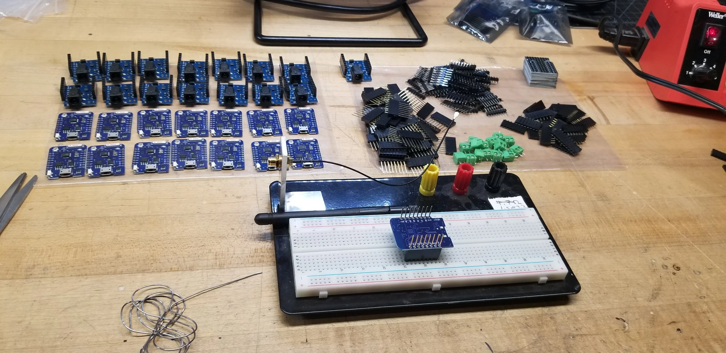
One of the marvelous things about creating with a 3D printer is that it frees up your hands to work on other things. You can be printing and still working on other things, which is primarily how I did the electronics for this piece. While my printer was busy, I got to work on building out the system to power and run the spotlights.
To do this, I landed on using a single controller to broadcast a signal over wifi to all of the spotlight mechanisms. Each of the faux camera spotlights would have an internal ID set by dip-switches, and only need power to be supplied to work. So I got to work figuring out the nuts and bolts of how this would work, and landed on using a pretty simple setup.
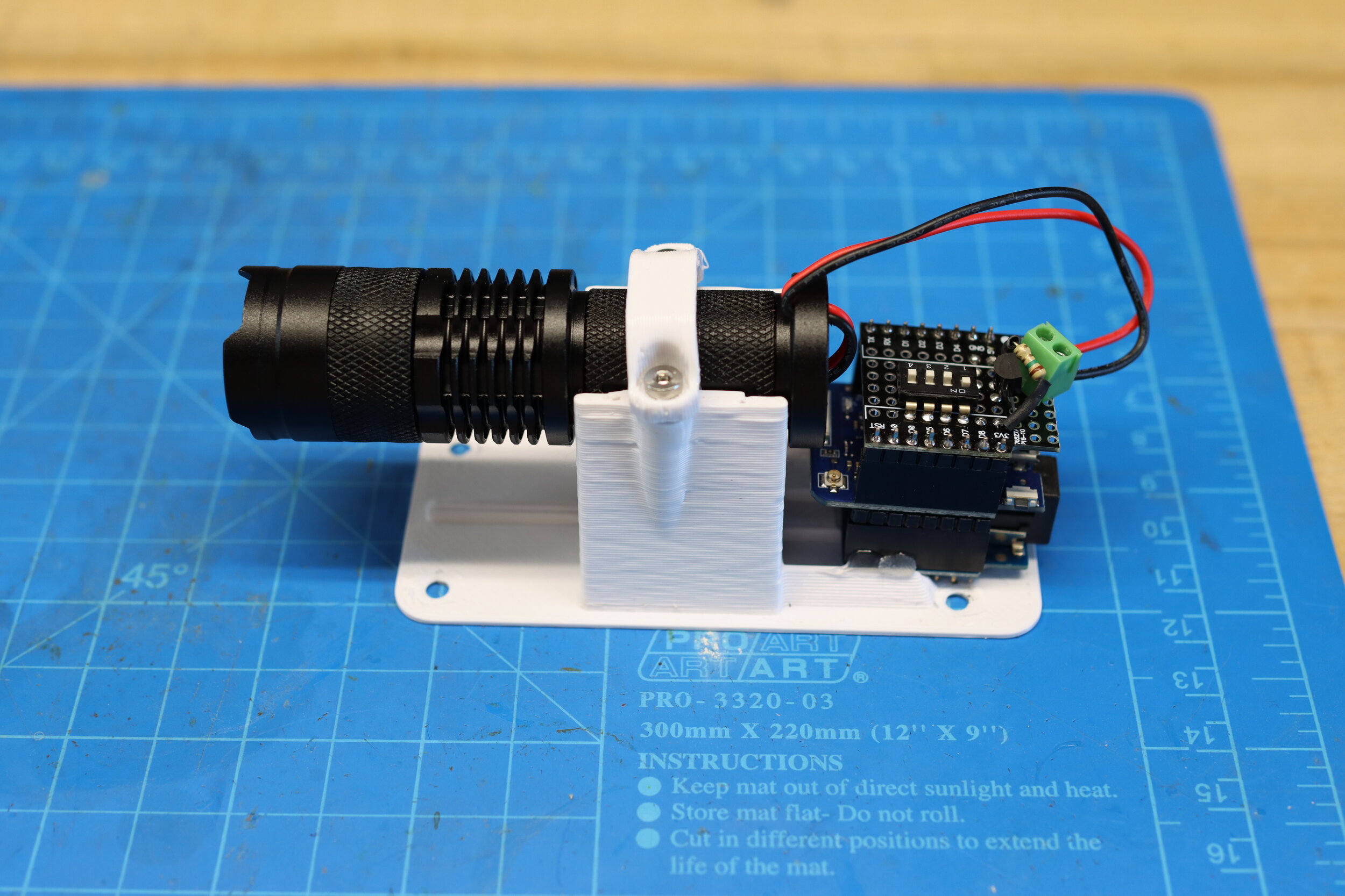
Each of the spotlights is run by an ESP8266 module which handles all the WiFi processes in addition to triggering the spotlight. The actual light source of the spotlight are LED Flashlights which ended up being simple to integrate. They’re already made to run for long periods of time, have a focus mechanism built in, and the aluminum bodies of the ones I selected worked well to dissipate any heat. Stacked on top of the ESP module I used is a small board that holds the dip switches and a transistor that regulated the power to the hot-wired flashlights. Powering it is a small step down module that took the 15 volts DC from a power supply and brought it down to the 3.3v that runs the light and microcontroller.
For the controller unit, I settled on using the M5 Stack Core ESP32 module. This ended up working very well, as it includes an LCD and buttons to build a UI on, an integral battery and charging via USB-C, and a SD Card slot that I used to load in the text read by the system.


But of course, all of the electronics are for naught if the there’s no code to run it. Overall, the way it operates is pretty simple…
The controller sequentially reads a character from a text file stored in the micro SD card.
The controller writes a log file to the SD card to save it’s place in the reading of the text file.
The controller takes the loaded character and interprets it into the series of 15 binary values that compose a 3x5 grid.
The controller, after a second has passed since the last time it sent out a message, then takes that string and broadcasts it to the spotlights.
The spotlight reads the value coded into it’s dip switches to determine it’s ID. That can be 1-15
The spotlight take the received string of binary values and compares it to it’s ID. If the value at its ID position is a 1, it turns on. If it’s a 0, it turns off.
Rinse, repeat.
The reading off of text from an SD card is something I’ve done a few times, but using WiFi is something I’ve only done once before. Rather than rely on using a galleries WiFi network (which can be spotty at the best of times), I ended up building a point to point network using a protocol specific to the ESP series of chips, called ESP-Now. It allows for devices that use it to communicate directly with each other, rather than needing to run all communications through a router. It’s awesome for self-contained art projects.
That said, I only came to using it after a ton of trial and error. For early versions of the code, I used a library called ‘Painless Mesh’, which turned out to be anything by painless. It had a number of dependent libraries that ended up conflicting with other libraries I was trying to use. On top of that, it was very resource heavy. Trying to run a proper mesh network (where every node connects to every other node) with 16 nodes was all together to much to ask a poor ESP 8266 to handle. It got to a point where it worked 90% of the time, but the whole system would occasionally lag and drop nodes for a few seconds, and that just was not good enough. So after weeks of fighting with it, I sat down and re-wrote all of the code to work with ESP-Now.
If you’d like to see how it came together, I’ve got the code for both the controllers and spotlight at the end of the post.

With the code working reliably, I did a final assembly of the pieces and set up the whole system to run for a while in my studio…


And just like that, it was time to de-install and bring it to the gallery. This piece was installed at the Installation Space in North Adams, MA as part of a Co-Show between myself and fellow artist Christina Balch. The show, titled “On Being Seen 👀” focused on privacy, in its form in public and in the home. I handled the ‘public’ side of the show, and made a few other pieces for the show, but I’ll get to posting about those later.
In the meantime, here’s a pretty spiffy vid of me aligning all of the spotlights into a grid…
All told, the show came together very well…
And is running well!
Learned a ton from this project, and it’s been very well received. It took a ton of time to put together, but now I’ve got a great project that can travel to various galleries.
Cheers,
Mac
Now for the goodies…
If you use any of these, please attribute. And shoot me a message! I want to see what’s made with them.
Arduino Code:
Controller/Conductor - Plays on an M5 Stack Core ESP32 module - [AScannerDarkly_TX-v3-00_RELEASE.ino] (24kb)
Spotlight/Player - Plays on a Wemos D1 Mini Pro (4mb) - [AScannerDarkly_RX-v3-00_RELEASE.ino] (4kb)
Case:
Faux Camera - Printed in PLA, looks best at 0.3mm layer height - [Thingiverse] / [Direct Download] (.zip, 929kb)