
Creating art out of a weapon. Using the Stuxnet Virus.
The Stuxnet virus was discovered in 2009, after spreading far beyond its intended target
When it was discovered and subsequently examined, it revealed just how sophisticated a virus could be. It was made to target one type of computer. It was made to be nigh undetectable. It utilized 4 zero day exploits to accomplish its incredibly narrow goal. It set a new bar in what could be accomplished with malicious code.
But perhaps its most lasting impact was how it irrevocably proved that code could be used to sabotage industrial equipment. This was not a new idea, having been demonstrated at the Idaho National Labs in 2007 during the Aurora generator tests. In that experiment, engineers used just 35 lines of code to totally disable a 27 ton diesel generator.
(You can read more about that here… Muckrock)

But those had all been tests. And just as the Trinity test had been a proof of concept, it was not useful until it could be weaponized. And that’s what makes the Stuxnet virus so remarkable. It is the first known instance of a computer virus being used to successfully attack a nation state’s material targets. In this case, Iran, which used specific digital controllers on the centrifuges that are used to enrich uranium to a state that could be used as fuel for powerplants (or weapons).
In brief, the Stuxnet virus spread by exploiting the way USB drives interface with the Windows operating system, allowing the worm to jump from system’s not connected via networking (known as an air gap). From there, it would lay dormant until the application used to program Siemens’ PLCs (Programmable Logic Controllers) was launched. At which point, Stuxnet would insert a smart bomb of malicious code into the PLC, which would only be activated if the controller configuration matched that of the centrifuges that had been acquired by the Iranians. Once activated, the code would lay dormant until the centrifuges were activated, at which point it would cause them to increase their RPM to the point of damaging themselves, or randomly opening valves to waste the extremely scarce uranium hexafluoride gas to be enriched. All while the machines reported back to their monitoring software that they were operating normally.
It is believed that these combined effects led to the wasting of millions of dollars in resources and caused a setback to Iran’s nuclear capabilities of at least a few years. All because of a set of code in total taking up less storage than the gif of the generator failing.
It is understood at this point that Stuxnet was a joint effort by NSA in the US and Unit 8200 of the Israeli Defense Force, even though both groups have not officially confirmed this. And why should they? There is nothing within the virus that directly points to them, and if they can operate with plausible deniability, it allows for more of these attacks to occur without repercussions for the responsible party. We only know as much as we do about this scheme because of the reporting by a host of security researchers and investigative reporters. I’m only able to scratch the surface here, but if you’re interested in learning more about Stuxnet, I’d highly recommend Countdown to Zero Day by Kim Zetter (ISBN - 9780770436193).
It was with the knowledge of this attack rattling around, and the recent 10 year anniversary of its discovery only having recently passed that I decided to start a deeper exploration of just what this sort of weapon could be. A clandestine digital weapon, the first of its kind, used to cripple another countries nuclear capabilities.
At the same time, I have been thinking about the tradition of portraiture of weapons of war. For instance, you can buy a framed print of the Enola Gay…
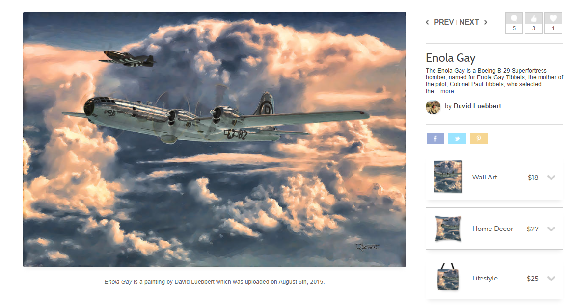
Which dropped a different kind of world changing weapon.
For as long as there have been armies and weapons, there have been fartistic depictions, both flattering and realistic. It goes counter to what most would consider as beautiful, depictions of the tools used in the ugliest human endeavor, but they serve a rhetorical purpose. These depictions showcase all of the wonderful aesthetic aspects of these tools, solidifying that imagery in the in the mind of those who consume it, while diluting the ramifications of their use. Glory and valor.
This idea has stuck with me as I grew up around them. My maternal grandfather served as a US Navy flight engineer in the Pacific theater of WWII and loved those machines. He had depictions of them scattered around their house. In addition, my role model for a successful artist growing up was a family friend named Patrick Haskett , who painted a variety of subjects including these sorts of portraits (And who unfortunately passed in 2014).
With those two influences in mind, I started work on what would become Portrait of a Digital Weapon.
The first task was to put down on paper and articulate the scope of what I was trying to communicate. When starting off with big ideas it’s easy to plan on doing everything that comes into your head, but one of the best skills I’ve learned is to sit down and come back to a design idea a few days after the first burst of excitement. More often than not the good ideas will all click together and the lemons will be easy to pick out. From there, I stick with those ideas and see it through. It will saves me a ton of time on the back end.

And yeah, I started this in 2019.
Next came the actual parts layout. I continued my trend from other projects based around the reading of a text using segment displays, but this was the first time designing a project with a segment display as a component rather than as the thing that constituted the majority of the piece. Learning from those past projects, I also designed a fixture type that would be a lot cleaner to install and wire.
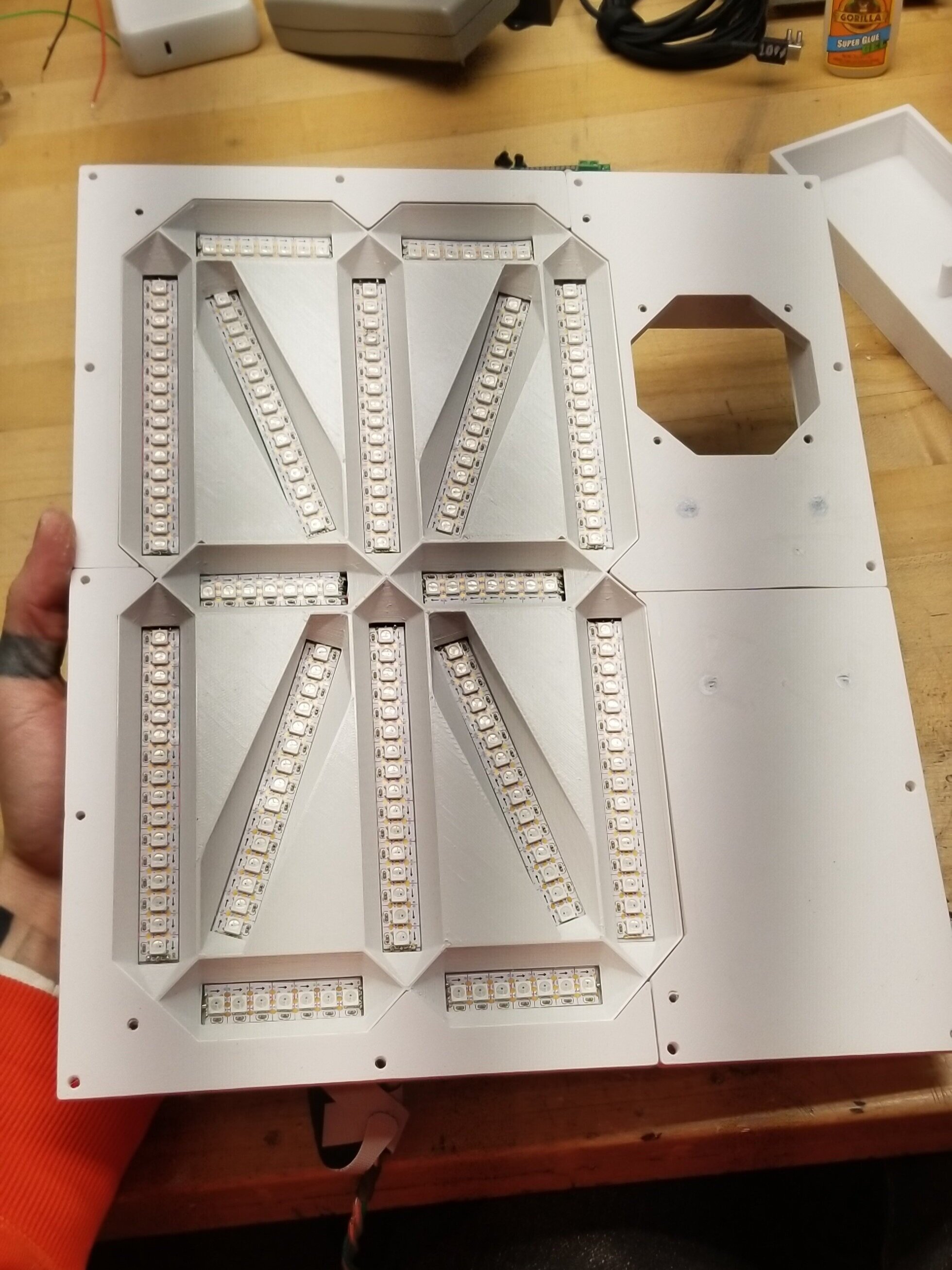
With this in mind, I ended up making a 16 segment character display, primarily because it’s available character space could display some of the non alpha-numeric characters used in code quite well. I started with a thin sheet of aluminum I applied a thin 3D printed layout template on, sized for the WS2812b tape I was using (If I recall correctly, 120px per meter), and then laid it all out…

And with a bit of wiring, and the addition of a few printed baffles, that turns into this….

204 LEDs, one power feed, one data feed. ✨
Next up was the interior frame. As all good portraits should have a gaudy frame, this one would be no different. I’d picked up an old antiqued frame somewhere along the way, but soon realized that the challenge was figuring out how to position and hold all of the electronics within that frame. A subframe was needed.
To make this piece, I modeled up all the components in relation to one another and in the spare space drew out a 3D printable fixture. As that subframe would be larger than the print space of my printer, I broke it up into 4 pieces that I later connected together with #2 studs and friction weld along the seams…


With the studs and friction welding, I was pleased to see that it held together incredibly well. With the whole frame being printed, it fit all the other components perfectly. (Pardon the banding on these photos, my desk lights interact with my phones camera in ways strange and unusual).
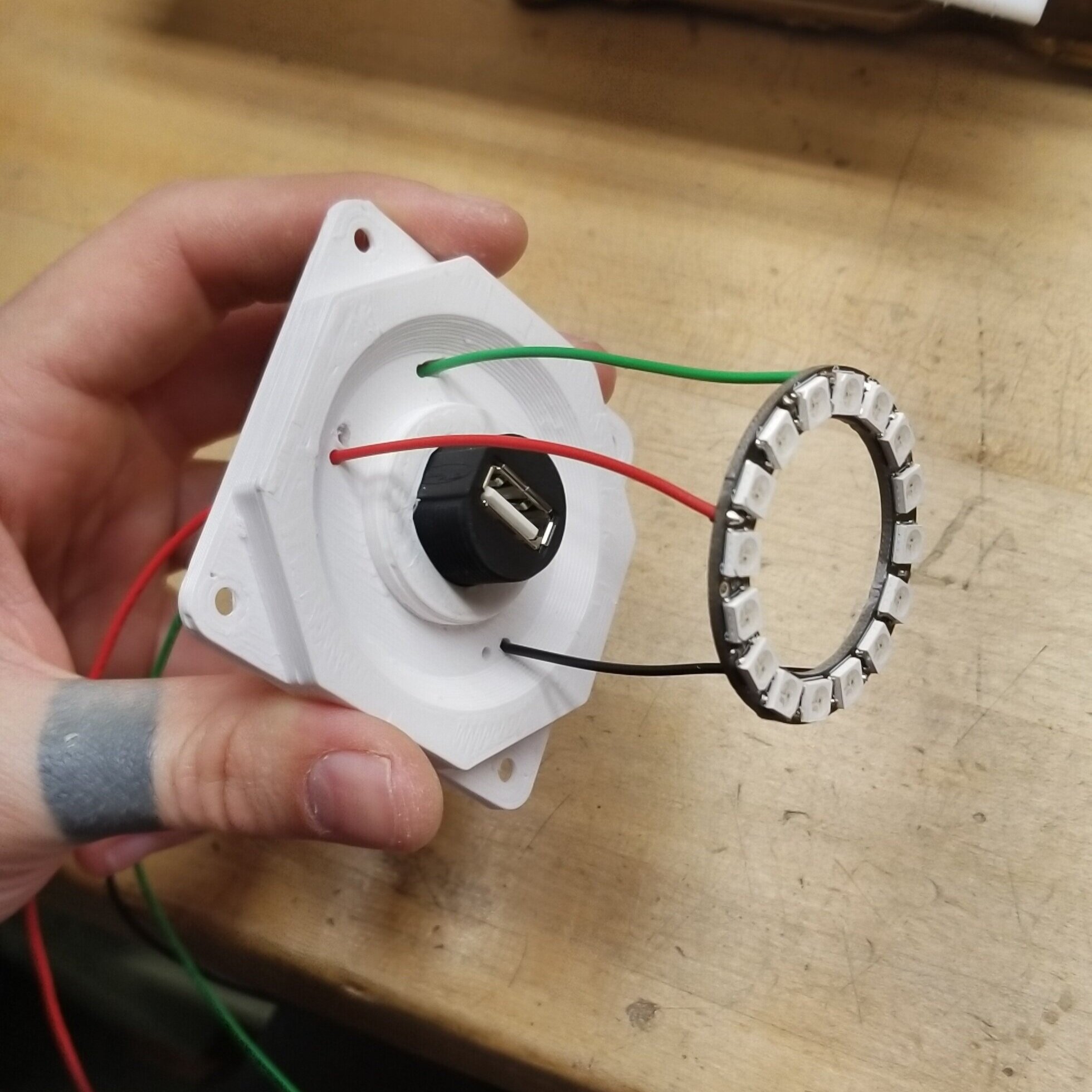
From this point it was just making the face and the USB ring, which involved making another printed piece to position the bulkhead USB connector as well as the WS2812b ring positioned around it.
The only thing left before jumping into the electronics was the face, which was actually the piece that hamstrung me the most.
See, I had started this project a long while back, but I’d wanted to work through all of the design components before I started making physical pieces. While often a prudent idea, in this case I hit a snag that kept me from progressing. I had wanted satellite imagery of the Natanz nuclear facility, but didn’t know how best to acquire it to then edit into the form I was planning on using. I’d considered google earth, but to get a useable image out of it would be pain. So I kept on thinking about what to do.
And kept on thinking.
And then I needed the workbench space, so I packed it all up and shelved the project.
And eventually I needed to move studios, and had to pack up again and move the project in its unfinished state.
So when I got to the new space and had unpacked, I decided to take another swing at it. Since I’d last set it down, I’d started following the work of Bellingcat, and had picked up a few of the techniques used by them to do open source reporting. One of which was the use of satellite imagery which was often facilitated through Sentinel Hub. After a bit of trial and error using their UI, I eventually found the spot I was looking for - 33.72415098779254, 51.72987662602709, the Natanz facility.

Which soon became this…

Which was then printed onto transparent vinyl and applied to a milky white polycarbonate sheet to become…

Nifty. A few screws through the face to attach it to the subframe and I was in business…

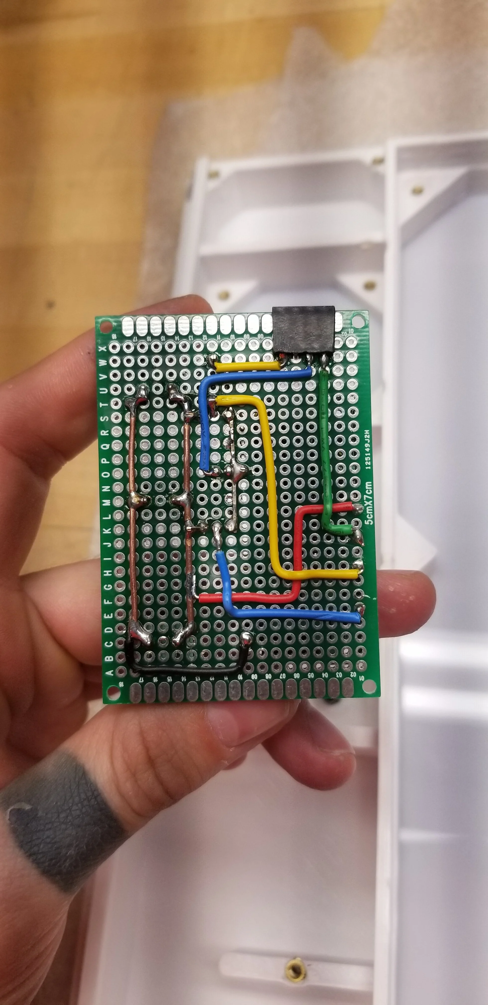
With all of the physical pieces in place, it was time to move onto the electronics. Which was all together pretty simple.
The backbone for this project is an Adafruit M0 Adalogger feather, which is a very capable little microcontroller. It has a built in micro SD card slot and waaaaay more than enough IO to push data to all the LEDs. For the two runs of WS2812b, one to the segment display and one to the USB ring, they each have a waste LED to act as a logic level shifter. As the M0 feather operates off of 3.3v logic and the WS2812b’s need a 5v signal for steady operation, I could have used a dedicated logic level shifter IC to bump up the signal, but it turns out that using a single LED to start the chain works out well enough.

This was a change from other projects of this vein that I had done is that instead of using a standard 5v wall wart to run this, I decided to use USB-C… For a number of reasons.
First, if the segment display is running full tilt at 100% white, it alone draws 20 watts, which is well outside of the standard 5watts (5v/1A) that can be reliable supplied by a standard USB-B connection. On top of that, USB-B cables only come at a maximum of 10ft. There are longer ones out there, but due to voltage drop for the 5v connection, it is not a great idea to use them. I wanted to be able to have the AC adapter as far as 20ft away for the convivence of mounting, and I needed at least 30w of power to make this thing run smoothly. Low and behold that’s easily done using USB-C’s PD specification. I’ve talked about how all this works in another blog post if you’d like to see more about it. In this particular instance, I am getting 12v from the AC adapter, sending it via USB-C cable to the port on the bottom of the electronics section of the subframe, where it’s bridged to a sink board that does the PD negotiation. After that, it gets passed onto a small buck converter to step it down to 5v, and then passed along to the electronics.


From there it was a matter of cutting the leads from the LED fixtures down to length and terminating them, and I was good to go… Until I realized that the Buck converter I was using was hot garbage, and could not maintain a constant ground under load. Whatever, easy enough to swap out.
Next up was the programming, which looks like this…
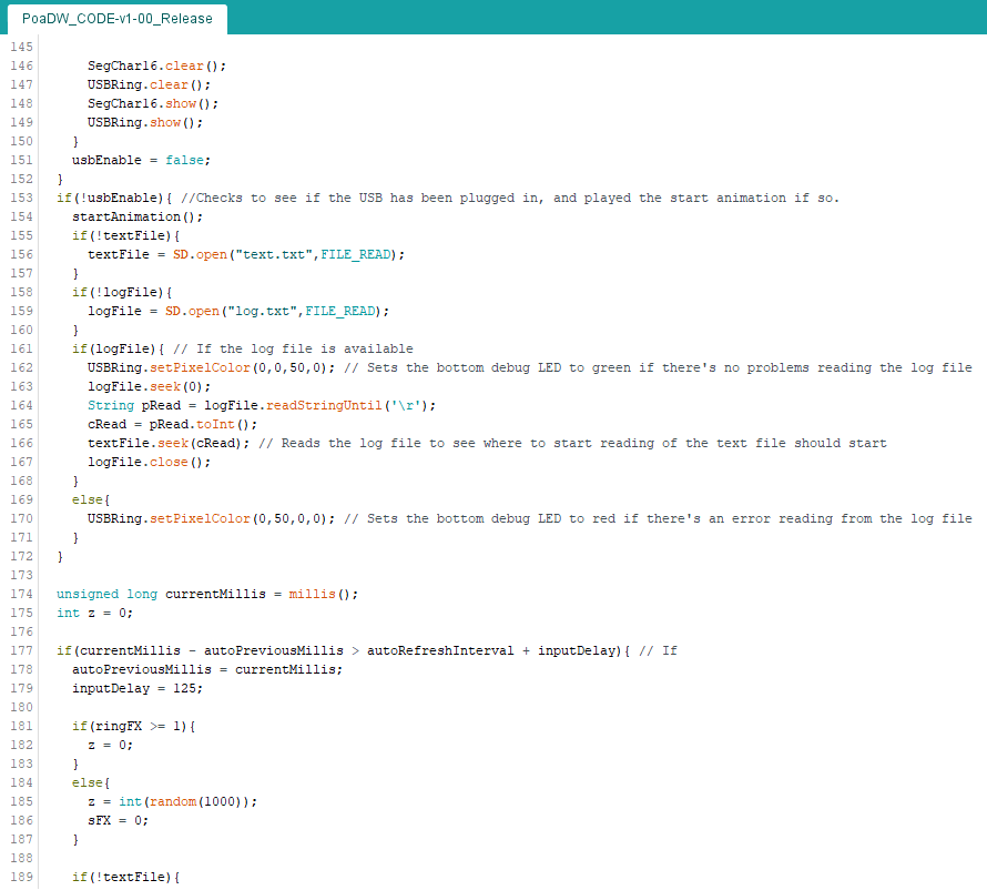
If you’d like to use the code that I made for this, have at it. Full project file here - (PoaDW_CODE-v1-00_Release.ino, 18KB) If you do use it, let me know! I’d love to see what you make with it. If you have code critiques, I am always open to constructive criticism.
The gist of what’s going on is that the microcontroller reads the decompiled text off of an SD card letter by letter. As it ingests the individual characters, it runs them through a function that compares them to a list of characters that the 16 segment display can show, and if it matches one of those characters (which is A-Z, 0-9, /, , , : , ; , = , + , { , } , ( , ) , [ , ] , . , ! , ? , @ , # , $ , % , - , _ , | , ^ , > , <, and a null char), it then checks it against the sequence of segments that need to be activated and then assigns each of the LEDs as either on or off. The USB LED ring also runs parallel to that function, and at randomized intervals will activate with it’s red “infected” animation, that simulates the speeding up of the centrifuges.
Running on top of all of this is a continuous check to see if one of the pins is reading low, which corresponds to the USB drive being plugged in. Turns out the GND line of a USB connection is connected through to the port’s metal rectangle on some USB drives, so if you check for a connected ground from the GND line to the port’s grounding connection, you can tell if its plugged in without needing to send any power to the drive. Easy way to make an enable switch that’s appropriate to the piece.
A quick note about where I sourced the decompiled virus from - Github! Someone uploaded the whole thing to Git in 2011. - https://github.com/Laurelai/decompile-dump - Of which it took only a bit of tweaking and cleaning up of comments to make into a text file readable by the Arduino.
After finishing the animations and tweaking the brightness and timing to make it less of BRIGHT BLINKY LED THING (LEDs running at 40% brightness, animations are slow), I was ready to document it.
One of the things I did upon moving into my new space was to set aside about half of the square footage as just a gallery / documentation area. Oh boy does that come in handy…

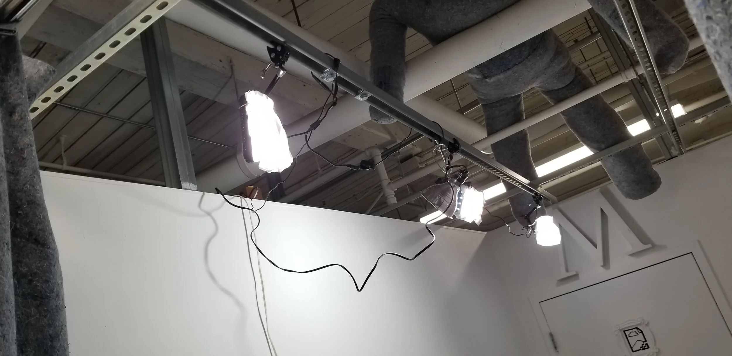
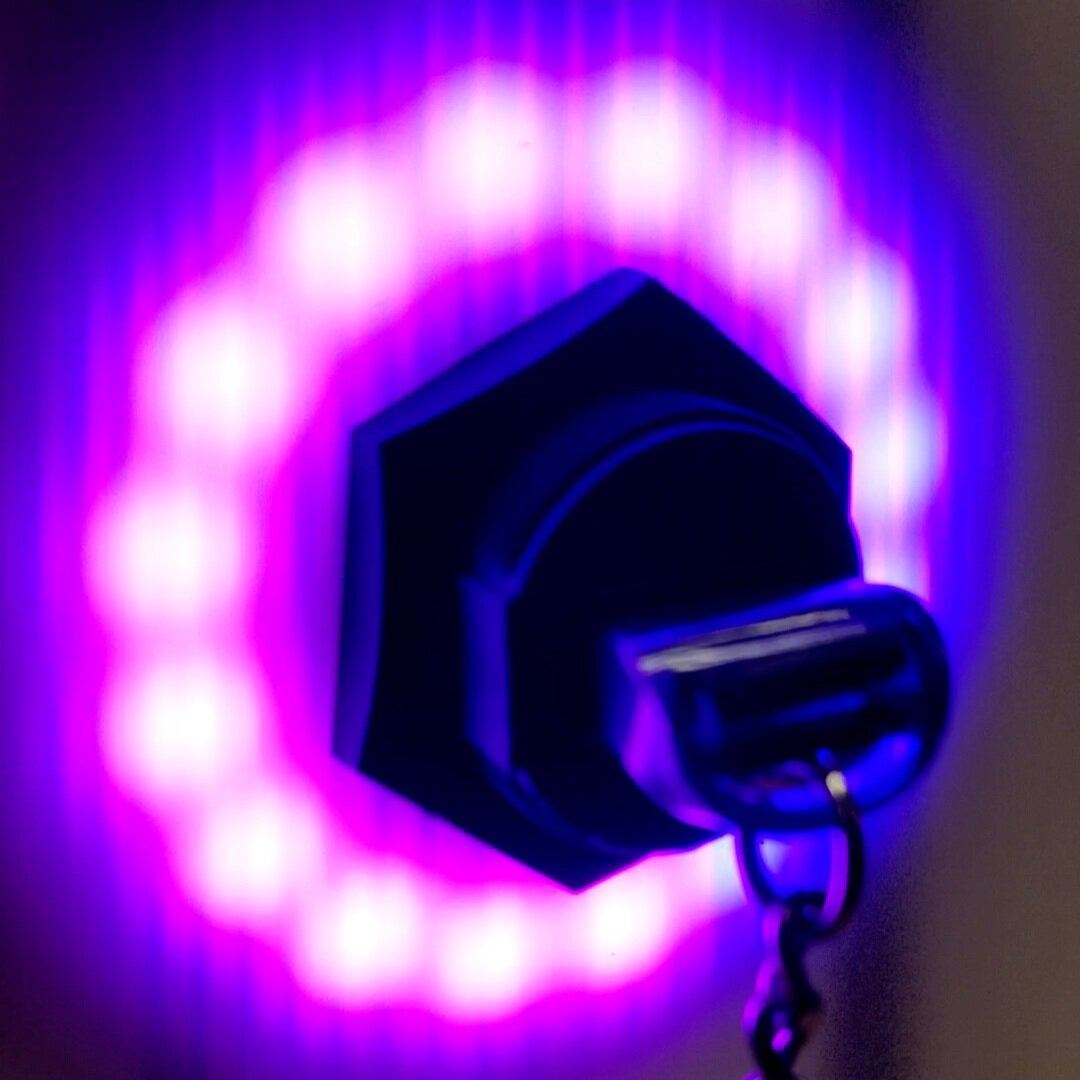
To produce images like this…

yessss.
And from there, a quick bit of filming and voiceover to make a project video…

And voilà, project and documentation complete.
The video in question (1m 35s)…
2,529,363 characters. That’s what it took to take down a nuclear program.
The Stuxnet virus and it’s decedents are only going to become more common, so getting this project together and released helps to provide a point of context for what is only becoming more prevalent. Cyber warfare is here to stay, and if these weapons are going to be used, we should at least acknowledge their existence. Maybe by painting their portrait.
Portrait of a Digital Weapon is the project that’s probably taken me the longest, from start to finish. Creative ideas come and go, but this one stuck with me. It needed to be realized. I learned a ton and it has opened up other avenues for art making that I’d like to pursue. Stay tuned!
Cheers,
Mac Pierce.